Get Fast Support From Our Sales Team
Get Fast Support From Our Sales Team
Need product information, quotation, samples, or delivery details? Our sales specialists will help you select the right TFT, OLED, AMOLED, or custom display solution.

Prepare an LCD display evaluation kit around the test the customer needs to run first. A useful kit pairs the exact display sample with a compatible way to drive it, the right cables and power information, and a quick-start guide that tells the receiving team what it should see on first power-up. It also identifies which parts match the proposed production configuration and which are temporary evaluation hardware.
That distinction matters when a kit goes from sourcing to an integration engineer. A working demo can establish that a panel displays an image. The OEM may still need to check whether its own processor can drive the panel, whether the flex cable fits inside the enclosure, and whether touch works through the planned cover glass. Agree on those decisions before choosing what to send.
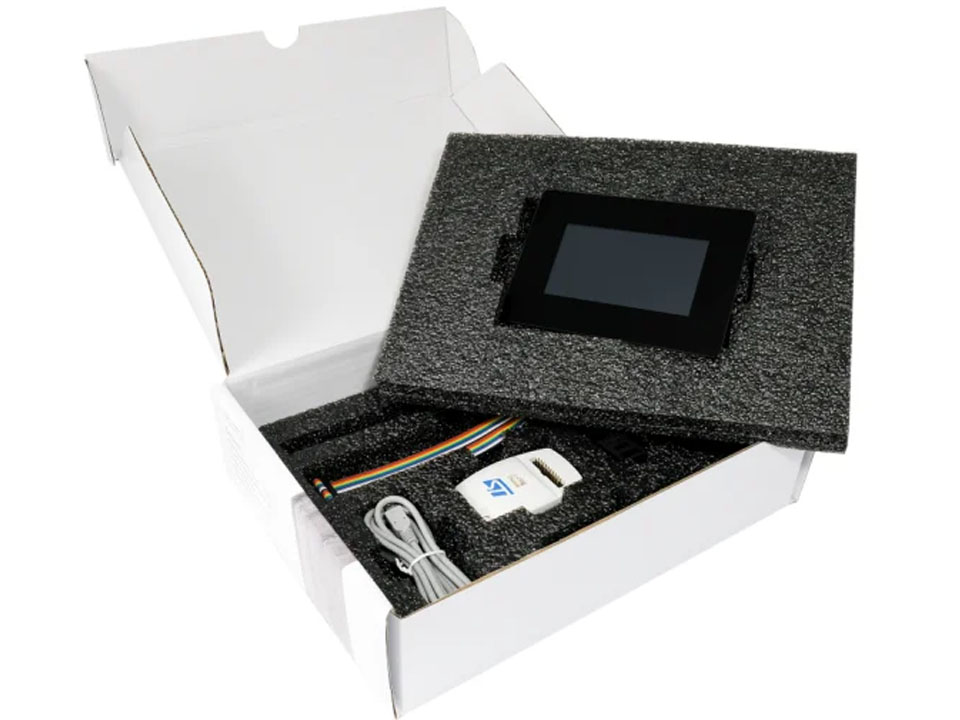
Ask the customer what decision the kit should support. If the team needs to compare appearance and readability, a known-good demo controller can get the screen running quickly. If the team needs to approve its own hardware and software, use the intended host or a representative development platform and document every difference from the production design. A kit can support both goals if it includes separate setup instructions and acceptance criteria for each.
| Evaluation setup | Use it to decide | Confirm before ordering |
|---|---|---|
| Panel with a preconfigured demo controller | Whether the image, viewing angle, or basic UI presentation merits further evaluation | Controller-to-panel compatibility, supported input, included power accessories, and whether touch is supported |
| Panel with a host adapter or interface bridge | Whether the OEM can bring up the display from its host platform | Signal path, supported timing, adapter and cable pinouts, firmware configuration, and backlight control |
| Production-intent display assembly with the planned optical stack and cable route | Whether the proposed assembly fits the enclosure and performs under the intended viewing conditions | Drawing revision, cover glass and touch stack, mounting method, harness, and any deviations from pilot hardware |
A more elaborate kit is worth the cost if it removes uncertainty the customer would otherwise have to resolve. For example, a preconfigured controller saves a sourcing team time during initial screening. For a firmware team testing native MIPI DSI, a simpler kit with the exact panel, documented adapter, and known initialization sequence can provide more relevant evidence.
Record the part number and available hardware or drawing revision. Attach the matching datasheet and mechanical drawing. The specification should identify the active area, module outline, mounting features, connector position, and flex exit direction. If the customer is choosing among Hicenda’s TFT LCD modules, ask the team to select the exact sample configuration, including touch or cover glass if those options affect fit or readability.
With a round opening, check how the visible area aligns with the bezel and where the flex cable exits relative to the enclosure. When reviewing Hicenda’s circular display options, confirm the active-area geometry and mounting orientation on the drawing for the selected model.
For a square instrument face, use the drawings for Hicenda’s square display modules to verify the bezel opening, UI margins, and connector clearance independently. These shape categories include options across display technologies, so identify the LCD variant by part number.
Optics-led projects need a separate evaluation plan. If the shortlist includes Hicenda’s microdisplay options, confirm the display technology, optical assembly, and viewing setup before reusing the direct-view LCD checklist. A near-eye evaluation may need a lens or an optical bench configuration to assess the image in the intended viewing system.
Document the signal path from the customer’s source to the panel. Show the connector at each end, cable orientation, and the board’s role in the path. For example, an HDMI controller may convert a standard video input to the panel’s native interface. A kit intended to validate the OEM host should identify the interface protocol, timing, lane or channel configuration where applicable, connector pinout, and any bridge settings. Include the touch interface separately if the panel has touch.
A bridge board can introduce its own configuration and power requirements. The Texas Instruments SN65DSI83 evaluation board overview gives a concrete example. It describes a DSI input, an LVDS panel connection, I²C configuration, and dedicated backlight circuitry on one evaluation board. For the kit you ship, verify each connection against the exact panel and board documents, including the flex cable’s contact orientation. A connector that fits mechanically can still have a different pin assignment.
Use a packing list that identifies the panel, controller or adapter, flex cable, other harnesses, and any supplied power accessory. State what the customer must provide, such as a video source, a host development board, or a compatible supply. Include a quick-start sheet, the correct drawings, and the firmware or configuration package used on your bench. A single kit ID on the box and on the document bundle makes it easier to keep later revisions together.
Before dispatch, give the packed kit to someone who did not build it and have them follow the quick-start instructions. If they need an extra cable, an unpublished firmware image, or a verbal explanation of a jumper setting, add that dependency to the kit or its instructions.
Start with a known test pattern and a recorded setup. Write down which input the board expects, how the cable is oriented, which power supplies are required, and what order the supplier specifies for connection and startup. Include a photo of the assembled bench setup and the expected result. For a customer-host evaluation, record the software build or configuration used for the baseline and any panel initialization settings the OEM needs.
Use the first session to answer separate questions:
If the backlight comes on but the screen stays blank, first reproduce the documented bench setup. Compare the cable seating, source output, and controller configuration against the known-good baseline. With a native-interface kit, check the panel’s documented timing and startup sequence before changing multiple settings. Record the first point where the actual result differs from the expected one. That gives the supplier a specific fault to investigate.
Give the LCD module, driver board, and cables separate compartments so the customer can check the contents against the packing list. Keep the flex clear of pinch points and prevent loose connectors or hardware from pressing against the display surface. Label each compartment and place the quick-start guide where it is visible when the kit opens.
Select protective packaging for any ESD-sensitive items based on the component handling instructions and your ESD control program. The EOS/ESD Association’s ANSI/ESD S541-2026 packaging standard defines properties for protective packaging used with ESD-sensitive items in production, transportation, and storage. Specify ESD protection, mechanical retention, and the outer shipper as separate packaging requirements. Check that the packed components stay seated and can be removed without pulling on the flex or connector.
If you’re preparing a branded kit for a customer demo, see Zhibang Packaging’s custom electronics boxes for examples of box and tray designs. Send the packaging supplier the dimensions of each component in its protective wrap, the combined kit weight, the intended opening sequence, and the shipping carton constraints. That gives the supplier enough information to size the compartments and quote a fitted insert.
Give the supplier enough information to quote the module, the hardware needed to operate it, and the configuration you expect to approve. Request separate line items for the display sample, controller or adapter, custom harnesses, and any engineering or tooling charges. A stock controller and a custom harness can carry different lead times. Ask which parts set the dispatch date and which items can be reordered for later builds.
| RFQ input | What the buyer should specify |
|---|---|
| Display and enclosure | Exact part number or target specifications, mechanical envelope, viewing window, thickness constraints, flex exit, and touch or cover glass needs |
| Host and software | Processor or development board, available interface, power available, cable constraints, operating system or firmware environment, and who handles initialization |
| Evaluation deliverables | Kit quantity, controller or adapter preference, drawing and configuration files, first-power-up test pattern, acceptance criteria, and target delivery date |
| Pilot and repeat orders | Expected pilot quantity, projected production volume, components that must match the approved kit, and how any substitutions should be handled |
Send Hicenda the host details, enclosure drawing, evaluation quantity, and test objective. Ask for a kit-level bill of materials, the first-power-up instructions, and a quote that identifies temporary demo hardware and production-intent parts. Before committing to the pilot, record the approved part numbers and revisions and ask the supplier to flag any proposed changes to the panel, touch stack, flex, or firmware.
Yes, if the standard module answers a defined question such as UI readability or basic host bring-up. Track differences in dimensions, interface, optical stack, and flex routing. Repeat the affected checks on a production-intent sample before approving the custom assembly.
Possibly. Ask for a compatibility list that covers the board revision, panel timing, pinout, power, and firmware profile for each sample. Label the matching harnesses and document the procedure for switching profiles or cables safely.
An HDMI demo kit can establish an image and support visual evaluation. To validate the production DSI path, test the intended host configuration, lane settings, timing, and initialization with the chosen panel and any bridge in the production design.
Include the planned cover glass when the decision depends on touch response or readability through the finished stack. For early software work, a temporary stack can be sufficient. Document its construction and schedule tests with the final thickness, coating, and mounting arrangement.
Send the exact part numbers and revisions, a photo of the wiring, the host and firmware details, and the last step that matched the quick-start guide. Report whether the backlight came on and whether the known-good setup still works.
Base the quantity on concurrent workstreams. One kit may cover a single bench evaluation. Separate kits can be useful when hardware, firmware, and mechanical teams are working in different locations. Identify any samples reserved for fit checks or handling trials when requesting the quote.
Leave Your Comments