Get Fast Support From Our Sales Team
Get Fast Support From Our Sales Team
Need product information, quotation, samples, or delivery details? Our sales specialists will help you select the right TFT, OLED, AMOLED, or custom display solution.
Need product information, quotation, samples, or delivery details? Our sales specialists will help you select the right TFT, OLED, AMOLED, or custom display solution.

An FPC is a flexible printed circuit with patterned conductors on a bendable base. Specify the outline, conductor layout, bend zones and contact geometry around your design. Compare constructions and check mating fit before you order prototypes or release a production build.
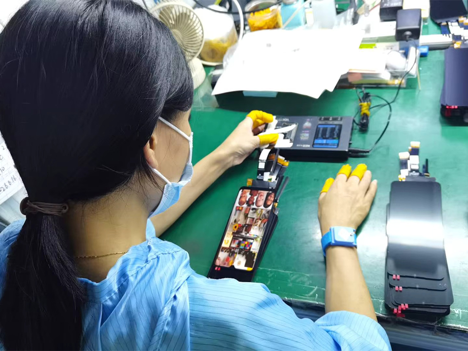
Choose a made-to-spec interconnect when the design needs a shaped outline, individually routed conductors or a place to mount components. An off-the-shelf FFC cable (flat flexible cable) suits a standard point-to-point connection when its length, pitch, position count and contact orientation match both ends.
An FPC cable can follow an irregular enclosure path, branch to multiple contact tails or connect pads in a pattern specific to your design. A wire harness is worth comparing when the product needs discrete wires to reach several locations, different wire gauges or separate terminations.
Start with the fewest copper layers that meet the electrical layout and mechanical requirements. These are general construction options. Confirm which combinations the supplier can build to your dimensions.
| Construction | Electrical Layout | Mechanical Considerations |
|---|---|---|
| Single-Sided | One conductor layer for simpler connections. | Generally easier to bend than a comparable build with more layers. |
| Double-Sided | Two copper layers give traces room to cross, with vias where a connection between layers is needed. | Check overall stiffness and keep vias outside active bend zones where possible. |
| Multilayer | Three or more conductor layers give dense layouts room for signals, power and ground planes. | Additional layers can increase stiffness. Confirm the bend requirements for the proposed build. |
Before production release, fit the prototype in the actual enclosure, verify pin mapping and retention, and run the electrical or functional checks needed for the application. Record the accepted materials, dimensions and drawing revision as the baseline for the production order.

Define what the supplier should deliver and confirm fabrication and component assembly as separate quote scopes.
| Build Scope | What to specify |
|---|---|
| Bare Circuit | Finished outline, conductor artwork, protective openings, contact finish and any required bare-part electrical checks. |
| Terminated Interconnect | Which ends use exposed contacts and which, if any, require an attached connector. Confirm any termination or installation work separately. |
| Populated Build | Solder pads, component locations and orientations, and access for probes or fixtures. Confirm surface-mount technology (SMT) and any required inspection or functional testing before including them in the order. |
A one-time installation bend is formed during assembly and stays in position. A dynamic bend moves in service, so specify the full travel, available inside radius, target cycle count and operating conditions. Show bend locations and directions on the drawing. Confirm the allowable radius for the proposed construction and validate repeated motion in the actual mechanism.
Use a stiffener where the contact tail needs support for insertion or a mounting area needs local rigidity. Identify the reinforced side, footprint and material. Check where reinforcement ends so the active bend stays clear of the transition.
Start with the exact mating part number and its drawing. For each end, check pitch, position count, contact side, pin 1 orientation and finished insertion thickness, including any local reinforcement. Confirm the required tail width, exposed contact length and locating features. Two parts with the same pitch can require different tail geometry or contact placement.
Specify exposed contacts where the tail mates directly with a receptacle. For a zero insertion force (ZIF) interface, check how the actuator opens, where the tail seats and how it locks. Call out a gold finger finish when the mating specification requires it and confirm the plating requirements for that exact part.
Agree on inspection criteria, any continuity and isolation testing, and the records required with each shipment. Confirm lot traceability and request applicable compliance declarations for the materials and finish on the quoted part.
Compare prototype and production quotes at the same revision. Ask how layer count, materials, finish, assembly scope and quantity affect pricing. Confirm minimum order quantities, lead times for each build stage, any one-time tooling charges and whether production will use the materials and process validated on the prototype. If either will change, agree on the approval steps before release.
Compare layer options, bend requirements and connector fit for made-to-spec flexible interconnects. Get a quote for your prototype or production build.
Choose one when your design needs a shaped outline, branched conductors or mounted components. A stock jumper can suit a standard point-to-point connection.
Start with one if it meets your electrical layout. Add layers for trace crossovers or dedicated power and ground, then check the effect on bending.
That depends on the construction and motion. Specify the available inside radius, travel and target cycle count, then test a prototype in the actual mechanism.
Check the exact mating part drawing for position count, contact side, insertion thickness, tail geometry and required plating.
Reinforce an insertion tail or component mounting area where it needs support. Mark the reinforced side and footprint, and keep the transition clear of active bends.
Ask for separate line items and confirm which scopes the supplier can provide. For a populated build, specify who supplies components and what testing is required.
7. What should I verify on a prototype?
Check enclosure clearance, latch access, pin mapping and electrical function. For moving parts, monitor continuity through the required motion cycles.
Ask for project-specific terms at prototype and production volumes. Layer count, materials, finish, quantity and any tooling or population work can affect the quote.
Confirm the approved drawing revision, materials, inspection criteria, test records and lot traceability. Agree on how changes from the validated prototype will be approved.
Send a dimensioned drawing or available fabrication files, mating part numbers, bend requirements and target quantities. Flag open decisions. Include a bill of materials and placement data for populated builds only.
Tell us about your flexible interconnect and the quantities you need for prototyping or production.