Recently, we received some problems from customers: when burning the display driver through J-LINK, the display screen will be obviously flickering, and this situation will gradually dissipate and back to normal. Although it does not affect for normal use, we still want to understand the reason.
When facing this such phenomenon, the first thing that comes to mind is that the control timing is wrong when burning the program, causing the liquid crystal state to not return to normal, which is a typical liquid crystal polarization problem. The following is a brief introduction to the working principle of TFT display.
1) Working Principle of LCD Screen
Liquid crystal has unique optical properties, and light will propagate along the crystal direction of liquid crystal. Therefore, liquid crystal will bend the direction of polarized light. Through appropriate arrangement, the polarized light after passing through the first polarizer can be rotated to pass through the second polarizer. As shown in Figure 1, by adjusting the voltage between the electrode plates at both ends of the liquid crystal layer to control the degree of distortion of the liquid crystal molecule arrangement, the amount of light passing through the second polarizer is controlled, and finally various colors are presented.

2) Polarity conversion
Since the driving voltage of liquid crystal molecules cannot be fixed at a certain value, under the action of a single polarity electric field, the liquid crystal molecules will undergo an electrolytic reaction in the DC electric field, causing the liquid crystal molecules to accumulate at the positive and negative poles according to their different charged polarities, resulting in polarization, and thus gradually losing their optical rotation characteristics and failing to function as a light valve. In order to avoid the destruction of the characteristics of the liquid crystal molecules, the driving voltage of the liquid crystal molecules must undergo polarity conversion.

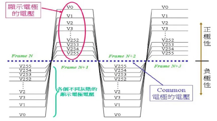
The voltage of the common electrode is fixed, and the voltage of the display electrode keeps changing according to the grayscale, as shown in Figure 2. When the voltage of the display electrode is higher than the voltage of the common electrode, it is called positive polarity, otherwise it is called negative polarity. But no matter whether it is positive or negative polarity, when the absolute value of the voltage difference between the two electrodes is fixed, the grayscale displayed is the same, but the direction of the liquid crystal molecules is completely opposite. Changing the polarity of the liquid crystal in this way can maintain the display content and avoid the destruction of the liquid crystal characteristics. There are four common polarity conversion methods, namely frame-by-frame inversion, row-by-row inversion, column-by-column inversion and point-by-point inversion. Among them, the display quality of point-by-point inversion is the best compared to other conversion methods.
3) Common liquid crystal polarization phenomena
The following are common liquid crystal polarization phenomena on display screens:
3-1:When the liquid crystal is static for a long time on a certain screen, when it switches to a grayscale screen, screen flickering occurs, but the screen flickering disappears after a certain period of time (usually a few seconds to a few minutes, which is related to the liquid crystal itself);
·
3-2:When the liquid crystal is static for a long time on a certain screen, the surrounding black and the middle white phenomenon occurs, and the white phenomenon disappears after shutting down or playing the video screen for a period of time; this phenomenon is called surrounding mura or black and white TV frame abnormality in the industry;
·
3-3:When the power is turned off illegally, the screen flickers when it is powered on again, and disappears after a certain period of time (usually a few seconds to a few minutes, which is related to the liquid crystal itself)
·
3-4:When the liquid crystal is static for a long time on a screen, the mirror image residue appears when switching to other screens, that is, the afterimage phenomenon;
·
4) Driving method of TFT display screen
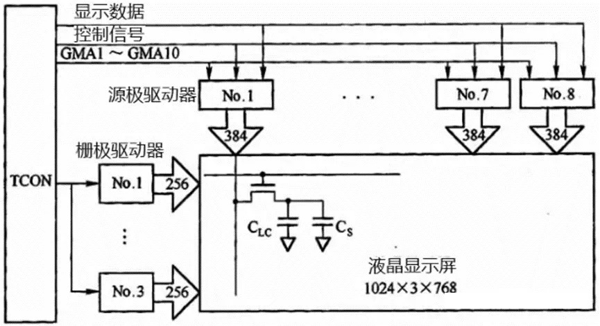
TFT liquid crystal display screen is an active matrix display screen, and its driving method is completely different from TN and STN liquid crystal screens. It adopts the "active matrix dynamic driving method". As shown in Figure 3, taking a 1024*768 resolution display screen as an example, the driving method of TFT display screen is briefly explained. In the LCD screen, the gate of each TFT tube is connected to the horizontal scan line, the source is connected to the vertical data line, and the drain is connected to the LCD pixel motor and storage capacitor. The display screen only starts one gate scan line at a time to turn on the corresponding row of TFT tubes. At this time, the vertical data line sends the corresponding video signal to charge the liquid crystal storage capacitor to the appropriate voltage, and then the image of one row can be displayed. Then the TFT is closed until the next time the signal is rewritten, so that the charge is stored on the capacitor, and the next horizontal scan line is started at the same time, and the corresponding video signal is sent. The video signal of the entire screen is written in sequence, and then rewritten from the first line. The frequency of this repetition is called the frame rate (refresh rate).

Next we will analyze the screen flickering problem based on the working principle of the TFT display.
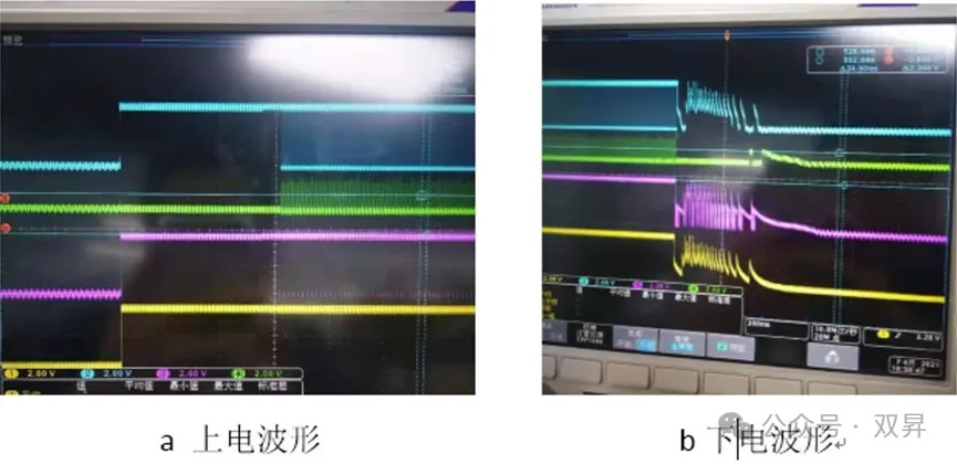
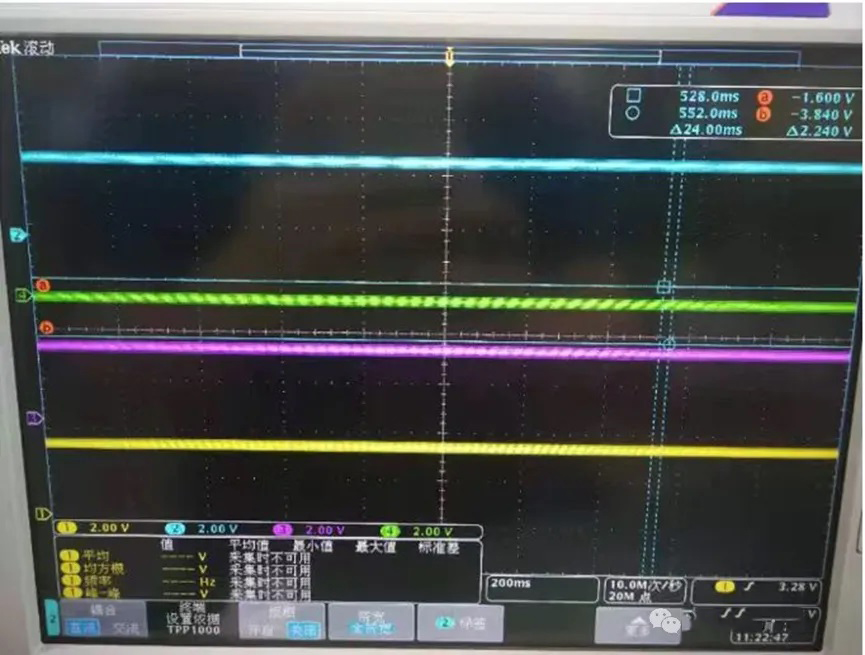
As shown in Figure below, the waveform of the display when it is powered on and off normally. The blue line is the field synchronization signal VSYNC, the green line is the line synchronization signal HSYNC, the purple line is the data enable DE signal, and the yellow line is the VCC signal. After powering on, the field synchronization signal changes periodically, that is, the polarity of the liquid crystal changes according to a certain period; when powering off, VSYNC, HSYNC, DE and VCC are pulled down synchronously, that is, the liquid crystal state is reset, and it will not remain at a certain polarity.
Therefore, it will not cause liquid crystal polarization, and will not cause the corresponding screen flickering problem.

Image below is the waveform during burning, and the corresponding signals of each color are the same as above. As can be seen from the figure, when burning starts, the data enable signal is high and still valid, and the horizontal synchronization signal is also in a low-level valid state, and the field synchronization signal is always high. This is equivalent to the entire burning process, the liquid crystal is always in a polarity state, and no polarity conversion is performed, which causes the liquid crystal polarization, and then causes the screen flicker problem. If the polarization state of the liquid crystal lasts long enough, it may even cause permanent damage to the liquid crystal and lose its optical rotation characteristics, that is, the display screen is damaged.

The J-LINK download method is generally only used for the first burning in production, so it will not affect the device experience and can be left untouched.
When burning the program, do not connect the display;
Before entering the burning state, initialize the relevant pins and pull them all low to reset the LCD state first;
Contact: David
Phone: +8618665976986
Tel: +8675521563288
Email: [email protected]
Add: 305 Room A Buiding Huafeng International Robot Industrial Park Xixiang Bao'an