
The main function of the TFT-LCD circuit is to control the voltage value on the two surfaces of the liquid crystal to control the deflection angle of the liquid crystal, change the twisting angle of the liquid crystal molecules to the linear polarized light, and finally control the intensity of the light passing through through the orientation of the polarizer in front. Thin film field effect transistors (TFT) correspond to each sub-pixel controlled. The thin film transistor TFT is a switching device, and its on and off states are close to ideal switches. Taking a display screen with a resolution of 1024×768 pixels as an example, each pixel consists of sub-pixels of the three primary colors of R, G, and B, that is, there are a total of 1024×768×3 TFT transistors. As shown in the figure below
--TN screen: twisted nematic (TN) liquid crystal display. It has a faster response speed and is less prone to ghosting; the viewing angle is lower (the maximum viewing angle is about 70 degrees); the output grayscale is less, and the picture color is whiter. TN screen has good dynamic performance and short response time, but poor color, which is suitable for computer competitive games that require speed.
VA screen: uses vertical liquid crystal molecules. It is well-balanced in all aspects and suitable for home use. The contrast ratio of VA panel is a major advantage, which can reach 3000:1. However, due to the high contrast ratio, pixel conversion takes longer, which makes VA panel prone to problems such as smearing and blurring. VA panel is also a soft screen, and plum blossom pattern will appear when touched with a finger, while TN panel will appear water pattern. Therefore, VA panel has the best contrast ratio, so the details of dark and bright parts are more outstanding, but the response time is the worst, which is prone to smearing and other phenomena.
IPS screen: In-Plane Switching, also known as "Super TFT". IPS screen uses horizontal liquid crystal molecules. Slow response speed and easy to have residual image; wide viewing angle (each viewing angle can reach 85 degrees); good color. Good color, good static performance, but long response time, suitable for general games such as LOL, watching movies, design, etc.
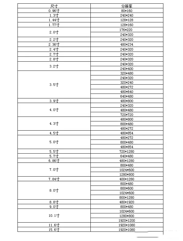
Resolution is the number of pixels. The number of pixels and the size of a single pixel determine the size of the display area.
TFT-LCD signal interfaces include SPI, MCU, RGB, LVDS, MIPI, eDP, HDMI, etc. Today we will talk about the characteristics and signal composition of the SPI interface (for different interface types, please refer to the specification of the relevant model. There are various LCD screens with different interface types for reference on our official website http://www.hicenda.com).
(1) SPI interface
As the name implies, the SPI interface is based on the SPI bus protocol to realize data exchange between the CPU and the LCD. This interface signal has many working modes, and the pin definition is usually: SDI (sometimes written as SDA) + SDO (available when needed) + SPI_CLK (sometimes written as SCK) + CS + power line. The advantages and disadvantages of this interface definition are also very obvious. Because the SPI communication protocol uses fewer wires, the LCD using this interface will relatively require fewer pins. However, because the data transmission is serial transmission and only a single data line is used for input, the software is more complicated and the transmission speed is slow. It is impossible to realize fast screen refresh operations such as video playback. However, it will have better display effects for a single screen, occupy less resources, and be simpler to control.
(2) MCU interface
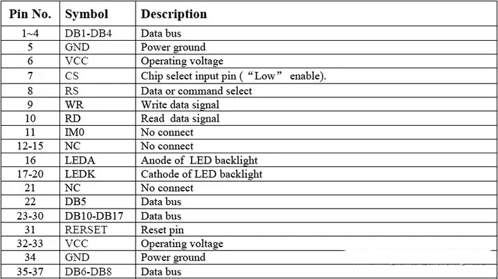
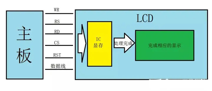
MCU interface is also called parallel communication screen, which can be divided into 8080 interface and 6800 interface. The principles of these two interfaces are the same, and the only difference is the timing. Multiple data lines are needed to realize the data interaction between CPU and LCD. This interface signal has many working modes, which can be subdivided into 8-bit, 9-bit, 16-bit, 18-bit, 24-bit and other interface modes. The pin definition is usually: CS (alias: chip select pin, usually used to select IC) + RS (alias: register select pin, usually used to set the storage location of the transmitted content, high level selects data register, low level selects instruction register) + RD (sometimes written as SCK) + CS + power line.
The advantages and disadvantages of this interface are also very obvious. Because the MCU interface occupies more resources, the LCD refresh speed using this interface is also faster than the SPI interface, and the software control is also simpler than the SPI.
Advantages: The refresh speed is faster than the SPI interface, it can be used in horizontal and vertical positions/vertical and horizontal positions, and the operation is simple and convenient
However, because the data transmission needs to be temporarily stored in the memory for processing, the refresh speed will not be very fast. Different products and different resolutions will have significantly different refresh speeds. Because it occupies more resources, the higher the resolution, the more GRAM it needs, so it is difficult to support large-size screens.
Disadvantages: It does not support video playback, cannot be large-sized, and occupies more resources.
(3) RGB interface
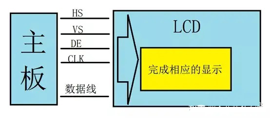
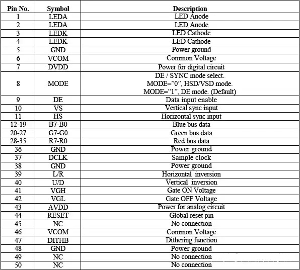
The RGB interface uses the three primary color data signals as the basis to realize the data interaction between the CPU and the LCD. There are many working modes of this interface signal, but without exception, all of them need to pass through multiple data lines. According to the different number of signal lines, the interface can be subdivided into several working modes such as 6bit, 16bit, 18bit, and 24bit. The pin definition is usually: CS (alias: chip select pin, usually used to select IC) + VSYNC (field synchronization signal, select the effective field signal interval on the LCD) + HSYNC (horizontal synchronization signal, select the effective horizontal signal interval on the LCD) + DE (data enable signal) + data line (R0~Rx, G0~Gx, B0~Bx, x=actual data/3-1, for example, if 24bit is used, x=24/3-1=7) + power line (VCC, GND, LEDA, LEDK, etc.).
This interface has both advantages and disadvantages. Because the RGB interface occupies more resources, the LCD refresh speed using this interface is very fast, and the software control is relatively simple. And because the display data of this interface does not need to be written into the memory for processing, it can be directly written into the LCD for display, so the response speed and refresh speed are much faster than the MCU interface.
Advantages: fast refresh speed, video playback, simple and convenient operation and control;
However, because the field-line synchronization signal needs to be set, the corresponding circuit must be set in the motherboard to cooperate with the software to control the frequency and data of the field-line synchronization signal. Some motherboard main control ICs have a reserved function for field-line synchronization, which leads to two situations for this screen driver. One is that additional circuits and software initialization are required to control the LCD driver; the other is that only software initialization is required to control the LCD driver.
Disadvantages: The control needs to increase the circuit, the software initialization needs to increase the program, and it takes up more resources;
(4) LVDS interface
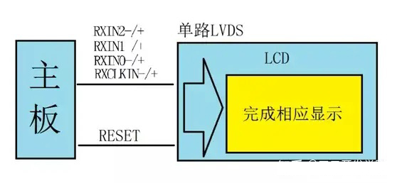
LVDS interface is the abbreviation of low-voltage differential signaling interface. Each data line is divided into two, positive and negative. Two low-voltage differential signal lines are combined into one data line. The data exchange between CPU and LCD is realized by combining multiple such data lines. There are many working modes of this interface signal. According to the different number of data lines, the interface can be subdivided into 1port and 2port. These two can be further subdivided into 3line and 4line modes. The pin definition is usually divided into two types:
First pin definition
Single LVDS: RXINx-, RXINx+ (if 3-line, then RXIN0-~RXIN2-/RXIN0+~RXIN2+, if 4-line, then RXIN0-~RXIN3-/RXIN0+~RXIN3+) + (RXCLKIN-, RXCLKIN+) + power line + RESET.
The second pin definition
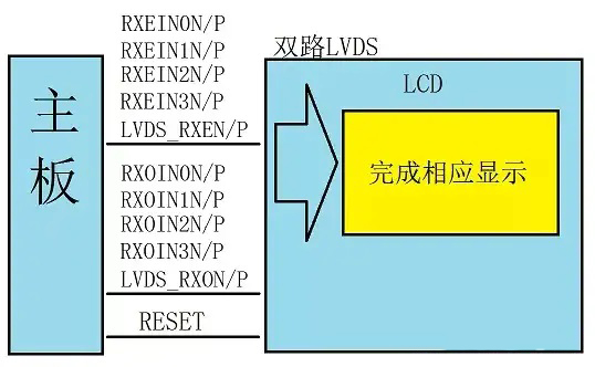
Dual-channel LVDS (divided into ODD channel and EVEN channel, which means it has twice as many data lines as single-channel LVDS):
RXOINx-, RXOIN+ (if it is 3-line, it is RXOIN0-~RXOIN2-/RXOIN0+~RXOIN2+, if it is 4-line, it is RXOIN0-~RXOIN3-/RXOIN0+~RXOIN3+) + (RXOClockIN-, RXOClockIN+) +RXEINx-, RXEIN+ (if it is 3-line, it is RXEIN0-~RXEIN2-/RXEIN0+~RXEIN2+, if it is 4-line, it is RXEIN0-~RXEIN3-/RXEIN0+~RXEIN3+) + (RXEClockIN-, RXEClockIN+) + Power line + RESET
This interface has advantages and disadvantages. Because it uses a very low-amplitude differential line to transmit signals, the noise generated will be very small, the power consumed will be very small, and the transmission rate can be as high as several thousand Mbps. Because the polarity of the differential signal is opposite, it can offset the electromagnetic field, so the interference they receive will also be very low.
Advantages: fast refresh speed, video playback, strong anti-interference ability, low power consumption, etc.
However, because the field and line synchronization signal needs to be set, the corresponding circuit must be set in the motherboard to cooperate with the software to control the frequency and data of the field and line synchronization signal. Some main control ICs do not support the LVDS interface and need to use a signal conversion chip for conversion, which increases the complexity of the motherboard circuit to a certain extent. There are also certain differences in the software, and the field and line signal parameters need to be set.
Disadvantages: It takes up a lot of resources, needs to add a signal conversion chip, the software is relatively complex, and instructions cannot be transmitted.
Contact: David
Phone: +8618665976986
Tel: +8675521563288
Email: [email protected]
Add: 305 Room A Buiding Huafeng International Robot Industrial Park Xixiang Bao'an
 hicenda
 David Dang